Sketch
Status: Implemented
Sketch stores 2D geometry in feature-persistent data and visualises it on a selected plane or face. The sketch mode opens a 2D sketcher environment where you can draft profiles that become the basis for Extrude, Revolve, Loft, or Sweep features.
Overview
Sketch Mode opens the 2D sketcher on a selected plane or face. Geometry is constrained within a local coordinate system, letting you dimension lines, arcs, and splines precisely. When you finish, the sketch remains parametric and updates downstream features as you edit it later.
Workflow
- Choose a plane or datum, then activate Sketch Mode from the feature history
- Draw with line, rectangle, circle, arc, spline, and text tools
- Apply constraints and dimensions to lock intent before returning to Modeling Mode
- Refine profiles with Trim, construction toggles, and spline edits
- Use the sketch as input for other features like Extrude, Revolve, Sweep, or Loft
Recommended Day-to-Day Flow
- Start rough: lay down the main profile shape first (lines/arcs/circles), without over-constraining.
- Clean topology: trim overlaps, close loops, and mark helper geometry as construction (
◐). - Lock design intent: use the context toolbar to add only the constraints needed for predictable edits.
- Dimension critical values: set distances/angles/radii that should drive the design.
- Finish and consume: exit sketch, then drive solids from the sketch with Extrude/Revolve/Sweep/Loft.
- Re-open safely: when upstream geometry changes, edit the same sketch and keep downstream features live.
Tool Icons
Sketch Mode uses Unicode icon buttons for quick tool switching. The top toolbar includes:
| Icon | Tool | What it does |
|---|---|---|
| 👆 | Select | Select and edit sketch points, curves, and constraints. |
| ✂ | Trim | Trim a curve at the nearest intersection(s) around the click. |
| ⌖ | Point | Create a point on the sketch plane. |
| / | Line | Create a line between two points. |
| ☐ | Rectangle | Create a rectangle from two corner points. |
| ◯ | Circle | Create a circle from center → radius point. |
| ◠ | Arc | Create an arc from center → start → end. |
| ∿ | Bezier | Create a cubic Bezier (end0 → ctrl0 → ctrl1 → end1). |
| ✍ | Hand draw | Draw a freehand stroke; on release it auto-converts to line/arc/circle or a Bezier fallback. |
| 🔗 | Link external edge | Project edge endpoints into the sketch as fixed points. |
| ↶ | Undo | Undo the last sketch operation. |
| ↷ | Redo | Redo the last undone sketch operation. |
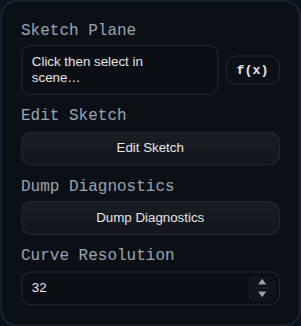
Inputs
sketchPlane– face or datum plane that defines the sketch basis. The plane orientation updates automatically when the reference moves.editSketch– button that opens the in-app sketcher (viewer.startSketchMode) so you can add points, curves, and constraints.dumpSketchDiagnostics– button that exports sketch/triangulation diagnostics for debugging.curveResolution– tessellation setting used when generating circular geometry for downstream features.
Behaviour
- The feature builds a local coordinate frame from the selected plane, saves it in persistent data, and reuses it on every regenerate so the sketch tracks its reference.
- Sketch geometry is kept as JSON, solved through the
ConstraintEngine, and rendered as aSKETCHgroup containing faces and edges that other features (Extrude, Revolve, Sweep) can consume. - External references are projected into sketch space at regenerate time and expression-backed dimensions are evaluated before solving.
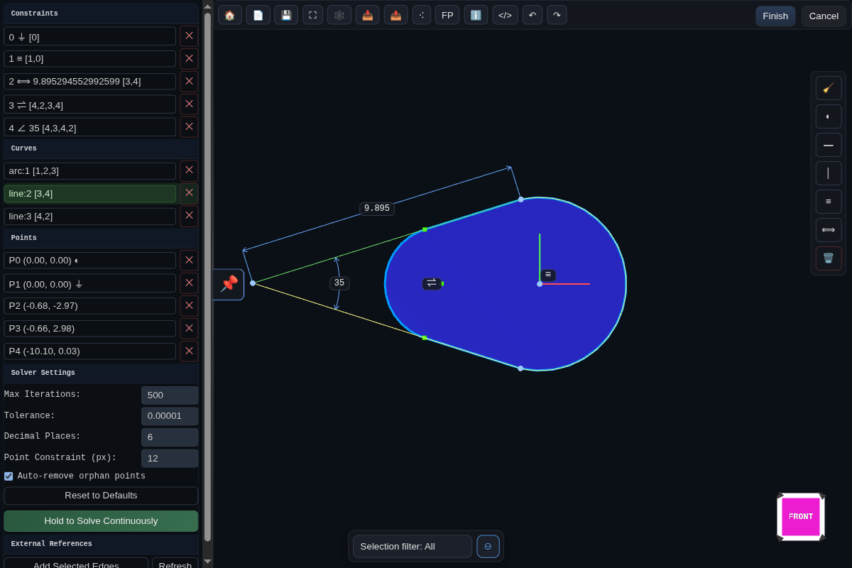
Constraints
Sketch constraints show up as glyphs that use Unicode icons so you can tell them apart at a glance. The solver supports the following set:
| Symbol | Constraint | What it does |
|---|---|---|
| ⏚ | Ground | Locks a point in place. Used for the origin and any projected references so they cannot be dragged. |
| ━ | Horizontal | Forces two selected points to share the same y value. |
| │ | Vertical | Forces two selected points to share the same x value. |
| ≡ | Coincident | Merges two points so they occupy the same coordinates; downstream coincident groups stay merged. |
| ⟺ | Distance | Adds a numeric dimension. On lines it fixes the segment length, on arcs/circles it becomes a radius or diameter dimension. |
| ↥ | Line to Point Distance | Adds a perpendicular distance dimension from a point to a selected line. Uses points [A, B, C] where AB is the line and C is the measured point. |
| ⇌ | Equal Distance | Makes two segments (or two radii) match length. Works for line pairs or circular features that need equal radii. |
| ∥ | Parallel | Keeps two lines travelling in the same direction, reusing existing horizontal/vertical locks when possible. |
| ⟂ | Perpendicular / Tangent | For line pairs it enforces a 90° angle. When applied between a line and a circle/arc it constrains the line to stay tangent by keeping the radius perpendicular at the contact point. |
| ∠ | Angle | Stores an explicit angle between two segments. The initial value is captured from the current sketch state. |
| ⏛ | Point on Line | Projects a point onto the line defined by the first two selections, useful for keeping construction points collinear. |
| ⋯ | Midpoint | Centers the third point midway between the first two and retains equal distances as you edit the sketch. |
Grouped constraints that touch the same points share a single anchor and render their glyphs side by side so complex regions stay legible.
Context Toolbar
A floating context toolbar follows the sketch viewport and updates itself based on the active selection. It offers only the constraints and actions that apply to the selected entities, making it quick to add intent without digging through menus.
Use selection as the main driver of what appears: select geometry, points, or constraints first, then apply one context action at a time and drag-test the result before adding the next constraint.
Context Action Icons
| Icon | Action | Selection context | Notes |
|---|---|---|---|
| 🧹 | Cleanup | Always available. | Remove orphan points that are unused by geometry and lightly constrained. |
| 🗑 | Delete | Any selected point, curve, or constraint. | Remove the current selection. |
| Fix / Unfix | Ground toggle | One or more selected points. | Adds or removes ⏚ ground constraints on the selected points. |
| ◐ | Construction toggle | One or more selected points or one or more selected curves. | Switch the selected points or curves between construction and regular sketch entities. |
| R | Radius | One selected arc or circle. | Create a radius dimension using a ⟺ distance constraint with radius display style. |
| ⌀ | Diameter | One selected arc or circle. | Create a diameter dimension using a ⟺ distance constraint with diameter display style. |
| ⏚ | Ground | One selected point. | Fix the point in place. |
| ━ | Horizontal | Two selected points, or one selected line. | Force the two points to share the same y value. |
| │ | Vertical | Two selected points, or one selected line. | Force the two points to share the same x value. |
| ≡ | Coincident | Two selected points, or one selected line. | Merge the two points so they occupy the same coordinates. |
| ⟺ | Distance | Two selected points or one selected line. | Add a numeric point-to-point distance dimension. For arc/circle radial dimensions use R or ⌀. |
| ⋯ | Midpoint | Three-point context, such as three selected points or one selected line plus one selected point. | Centers the third point between the first two points. |
| ⏛ | Point on Line | Three-point context, such as one selected line plus one selected point. | Constrains the third point onto the line through the first two points. |
| ⏛ | Point on Line | Two selected lines. | Adds point-on-line constraints that keep both endpoints of the second line collinear with the first line. |
| ↥ | Line to Point Distance | Three-point context, usually one selected line plus one selected point. | Add a perpendicular distance dimension from the point to the line. |
| ∠ | Angle | Three selected points, or one selected line plus one selected point. | Add an angle dimension for the three-point context. |
| ∥ | Parallel | Two selected lines. | Keep both line directions parallel. |
| ⟂ | Perpendicular | Two selected lines, or one selected line plus two selected points. | Enforce a 90 degree relationship. |
| ∠ | Angle | Two selected lines. | Add an explicit angle dimension between the lines. |
| ⇌ | Equal Distance | Two selected lines. | Make the two segment lengths equal. |
| ⇌ | Equal Radius | Two selected arcs/circles. | Make both radii equal. |
| ⟠ | Tangent | One selected line and one selected arc/circle. | Creates a ⟂ constraint between the line and the relevant radius so the line stays tangent. |
| Reverse Angle | Reverse angle | One selected ∠ constraint. | Swap the angle measurement to the opposite side. |
| Alternative Angle | Alternative angle | One selected ∠ constraint. | Flip the first line direction and measure the other arc. |
Trim Tool
Trim removes the clicked segment of a curve using the closest intersection(s) around the cursor.
- Activation – Choose the ✂ Trim tool from the top toolbar, then click the curve segment you want to remove.
- Supported geometry – Lines, arcs, circles, and Bezier splines can be trimmed.
- Local splitting – Trim only splits at the nearest intersection(s) around the click, not at every intersection along the curve.
- Closed curves – Circles (and full arcs) keep the segment opposite the clicked section.
- Degenerate cases – If a curve lies on top of another curve or an endpoint already sits on another curve and no valid trim bounds exist, Trim removes the curve entirely.
- Constraint preservation – When trimming against a line, the new trim point is constrained colinear to the cutting line (or coincident if it lands on the cutting line endpoint). For arcs/circles, trim points receive an equal‑distance constraint from the center to preserve the radius. Splines currently trim without adding constraints.
Spline (Bezier) Editing
The sketcher includes direct Bezier editing with construction‑line helpers.
- Creation – The ∿ tool creates a cubic Bezier using four points: end0 → ctrl0 → ctrl1 → end1.
- Construction guides – After creation, construction lines connect each endpoint to its adjacent handle so you can constrain handles with regular sketch constraints.
- Insert point – With the Bezier tool active, clicking near an existing Bezier inserts a new anchor at the closest location. The curve is split using de Casteljau so its shape is preserved, and new handle points plus construction guides are added.
Hand Draw Tool
The ✍ hand draw tool lets you sketch a stroke directly on the plane and automatically converts it into clean sketch geometry.
- Auto‑vectorize – On stroke end, the system detects lines, circles, or arcs; if nothing fits it falls back to a Bezier curve.
- Endpoint snapping – Stroke endpoints can auto‑snap to existing sketch points with coincident constraints based on the current zoom and the
Point Constraint (px)threshold in Solver Settings.
Visual Feedback
- Under‑constrained points – Points that are not fixed and are not referenced by any non‑temporary constraint are rendered in orange to flag areas that still need intent.
Solver Settings
The sketch sidebar exposes solver settings for iteration count, tolerance, and decimal precision. It also includes:
- Auto‑remove orphan points (default on) – After delete and trim operations, the sketcher removes points that are not used by any geometry and either have no constraints or only a single coincident/point‑on‑line constraint. This is the same logic used by the 🧹 cleanup action in the context toolbar.
- Point Constraint (px) – Sets the screen‑space snap distance used for automatic coincident constraints when drawing or manipulating points.
Linking External Geometry
Sketch Mode can link to edges that live outside the current sketch so profiles stay tied to upstream solids:
- Switch to the sketch and pick
Link external edgeon the top toolbar. - Click scene edges or face boundaries; each pick projects both endpoints into sketch UV space and adds them as fixed points.
- The viewer lists every linked edge; selecting a row reselects its projected points, and
Unlinkremoves the pair and their auto-created ground constraints.
The sketch feature stores external links as externalRefs in persistent data. On every regenerate it looks up the referenced edge by id or name, reprojects the endpoints into the sketch plane, and reapplies ⏚ constraints so the references remain locked. If the source geometry moves, the sketch updates automatically, keeping downstream features live without requiring you to redraw or manually re-reference the outline.